RoboCraft: a reconfigurable three-arm SCARA cell
Three SCARA robots that work alone or lock onto a hexagonal platform and become one parallel robot.
- When
- Since 2019
- Origin
- Bachelor thesis, rebuilt as a ROS 2 system
- Built with
- ROS 2 Humble
- Gazebo Fortress
- ros2_control
- C++17
- Python
- OpenCV
- Raspberry Pi
- ATmega
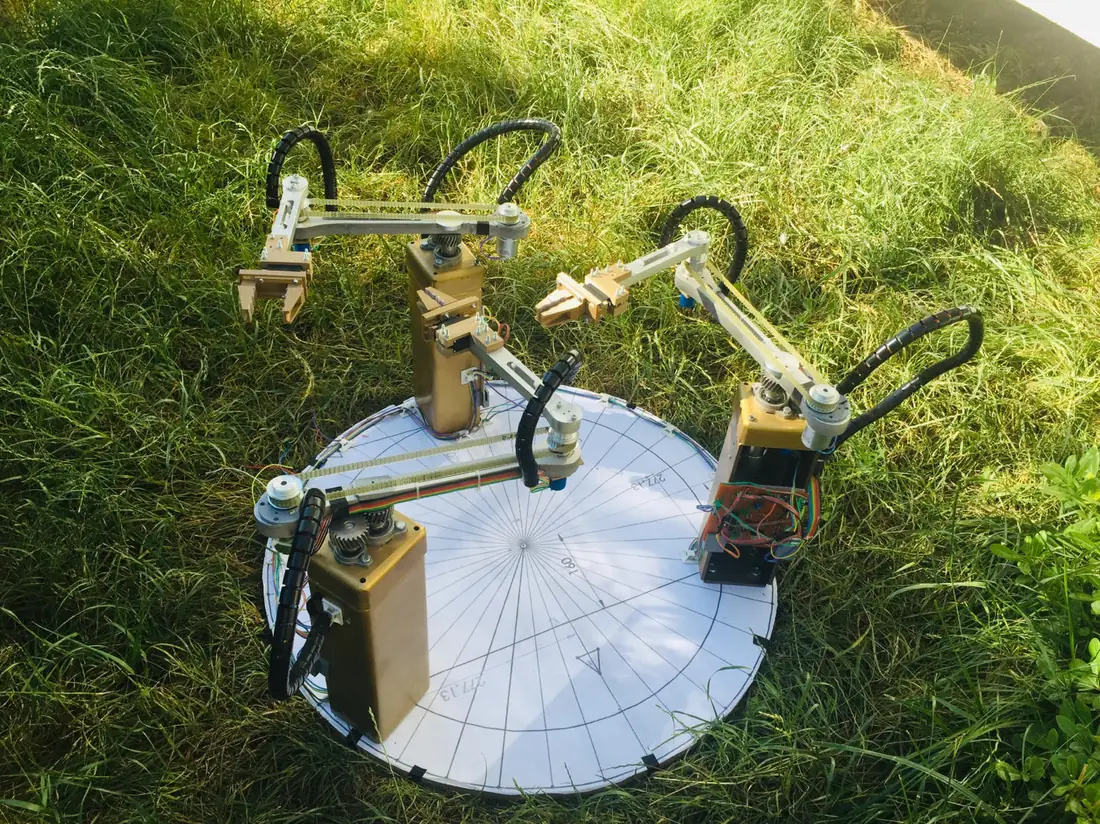
It started in 2019 as my mechatronics graduation project, funded by TÜBİTAK 2209-A: I designed, manufactured, wired and programmed a real prototype with six motors and three degrees of freedom. I have since rebuilt it as an industrial-style ROS 2 and Gazebo system with eight application scenarios, a verified engineering analysis and a driver for the real hardware.
The cell switches between two modes by itself. As three independent arms it tends three stations on one table. Coupled to the platform it becomes a 3-RRR parallel manipulator that is stiffer and can rotate a workpiece through 360°.
What the cell can do
Every scenario runs unchanged in unit tests, on mock hardware, in Gazebo and on the real robot.
| Scenario | Real-world task |
|---|---|
| Vision sorting | Camera quality inspection, defective parts to the reject bin |
| Laser cutting profile | Cutting a plate with a bolt hole |
| Obstacle square | Cutting around a clamp found by the camera |
| Serial pick and place | Three machine-tending stations sharing one table |
| Pure rotation | Turning a workpiece 360° by handing it between robots |
| Locked transport | One robot moving a fixture alone with the brake engaged |
| Parallel square, reconfiguration | Laser engraving and switching between tasks |
Measured results
- The laser path measured in simulation matches the 100 × 70 mm part, and the camera locates parts to within 3.5 mm.
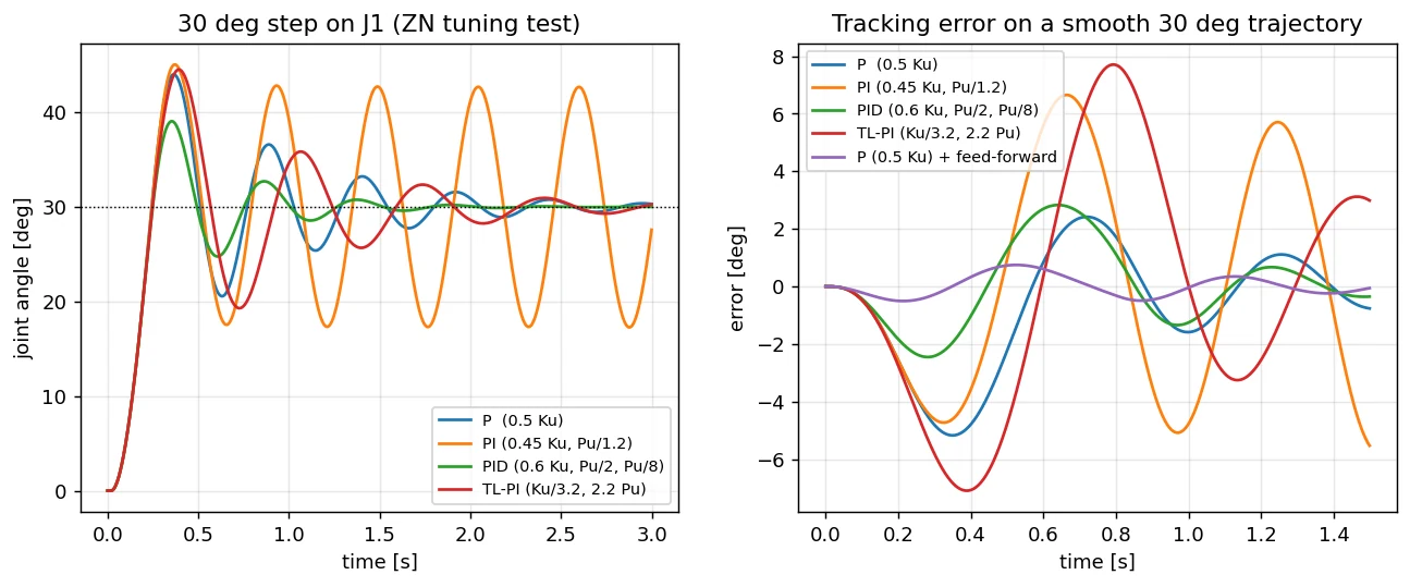
- Ziegler–Nichols gains with velocity feed-forward cut the tracking error from 5° to 0.75°.
- Peak joint torque is 2.18 N·m at full speed, which leaves the 42 kg·cm motor a 1.6× margin.
- Link deflection is 0.29 mm against a 2.5 mm limit.
- The analysis also explains why the first prototype was imprecise: a 10-bit ADC on a 10-turn potentiometer gives 27 mm steps at the tool tip. An encoder or a 16-bit ADC fixes it.
What is in the repository
Seven ROS 2 packages (model, kinematics, control, scenarios, Gazebo plugin, hardware), 39 automated tests with CI, eight analysis scripts that recompute the thesis design, the ATmega firmware with a CRC-checked I²C protocol, and the original 2019 thesis.